
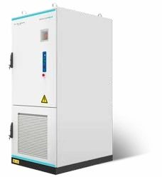
The SOLVA RT261 integrates 261kWh of high-voltage lithium iron phosphate storage with a 125kW rectifier for direct DC-bus charging and external central or hybrid inverter integration. The 125kW rectifier is not a 125kW load-supplying inverter. Understanding that distinction is essential when considering RT261 for a commercial site concerned about grid quality or continuity. SOLVA technical brochure, p. 14.
What does dual conversion mean in this arrangement?
A rectifier converts incoming AC electricity to DC. An inverter converts DC to AC for the connected loads. In RT261, these are separate functions: the integrated rectifier provides the charging path, while an external inverter forms part of the load-supply design. SOLVA technical brochure, p. 14.
| Function or parameter | RT261 specification |
|---|---|
| Battery energy | 261kWh total; 90% system depth of discharge |
| Integrated conversion equipment | 125kW rectifier |
| Rectifier AC input | 400V; three-phase, neutral and protective earth |
| External inverter connection | Integrated DC busbars rated for 125kW |
| Nominal battery voltage | 832V DC |
| Operating voltage, minimum to maximum | 728–936V DC |
Source: SOLVA technical brochure, p. 14. Rectifier power, DC connection rating and external inverter AC output must be kept distinct.
RT261 uses a transformerless rectifier. Dual conversion therefore does not itself provide galvanic isolation. The system designer must establish the electrical separation, earthing and protection arrangements required for the installation. SOLVA technical brochure, p. 14.
Turn a grid-quality concern into an engineering brief
RT261 is designed for applications where poor grid quality is a concern, with a transition to off-grid operation intended to avoid a voltage dip. The response at the site depends on the external inverter, controls and connected loads. Specify the acceptable interruption limits and validate the proposed system against them before relying on it for a critical process. SOLVA technical brochure, p. 14.
List the events that matter: voltage disturbances, complete outages, equipment resets or interrupted production. Supply monitoring records if available, identify the affected equipment and define the acceptable voltage and interruption limits with the relevant equipment supplier. This gives the design team an outcome it can evaluate and test.
Build an incident record around affected processes
For each event, record its time, the equipment affected, the observed interruption and the recovery action. Note whether production stopped, equipment reset or an operator intervened. Where monitoring is available, give the engineer the original records rather than only a description such as “the power is unreliable”. The purpose is to connect an electrical event with an operational consequence that the proposed system can be assessed against.
Ask which additional measurements would distinguish a supply disturbance from a problem elsewhere in the installation. Have the project team identify the measurement points and the required recording detail before commissioning a monitoring exercise. This avoids collecting information that cannot answer the design question.
Define the supported process completely. If a machine depends on controls, communications or auxiliary equipment, ask which of those items must share the proposed protected supply. The acceptance criteria should describe the process outcome and the equipment response, rather than assuming that energising one circuit demonstrates continuity.
Account for loads and recharging at the same time
Consider a hypothetical power balance, rather than a product performance forecast. Assume 125kW is available at the DC bus after rectification, and an external inverter draws a constant 80kW from that bus. Ignoring all other consumption, 125 − 80 = 45kW remains for battery charging. Restoring an assumed 90kWh at that constant rate would take 90kWh ÷ 45kW = 2 hours. The 125kW nameplate figure is from SOLVA technical brochure, p. 14; the load and charging assumptions are illustrative.
This is not an RT261 recharge-time specification. It assumes that the equipment permits the stated simultaneous power flows and that charging remains constant. Actual rectifier output limits, source capacity, auxiliary consumption, conversion losses, battery charge limits and state of charge need assessment. The 80kW is DC draw, not promised AC power at the loads. Ask the proposal to show both the load-supply and battery-recovery schedules.
Check recovery when the source contribution is restricted
Vary the hypothetical example by assuming only 105kW is available at the DC bus after rectification while the external inverter still draws 80kW. Ignoring all other consumption, charging has 105 − 80 = 25kW available. Restoring the same 90kWh would then take 90 ÷ 25 = 3.6 hours at a constant rate. Neither the 105kW condition nor this duration is an RT261 product rating.
If that assumed recovery opportunity lasts only three hours, the arithmetic permits 25kW × 3h = 75kWh, leaving 15kWh of the assumed 90kWh requirement unrecovered. This remains an idealised power balance, with no conversion or auxiliary allowance. Its purpose is to expose the importance of the recovery window, even when the equipment's headline rectifier rating has not changed.
Ask the design team to identify the source limitations that apply to the actual project and the proposed response when charging cannot keep pace with the operating schedule. Agree whether a restricted condition changes the supported load, the reserve objective or the next operating period. Those choices need an explicit operating policy.
Compare RT261 with AC261 by function
AC261 includes an integrated 125kW PCS and 400V AC output. RT261 includes an integrated 125kW rectifier and 400V AC input, alongside external inverter integration. Their shared 261kWh capacity does not make the two cabinets interchangeable. Compare the entire proposed conversion and switching arrangement. SOLVA technical brochure, p. 6; SOLVA technical brochure, p. 14.
The AC261 guide explains the integrated PCS option. For the external inverter questions, use the DC261 integration checklist and seek RT261-specific confirmation through FWA's inverter compatibility information.
Assess transitions and maintenance as separate requirements
Have the supplier describe the intended sequence for normal supply, loss of supply and restoration. For each state, identify the source feeding the DC bus, the external inverter's role and the conditions that permit battery charging. Ask what the operator will observe and which actions, if any, require intervention.
Then consider equipment maintenance separately from a grid event. Request the proposed arrangement when the rectifier or external inverter is unavailable, including any maintenance supply or bypass arrangement offered. Do not assume that the dual-conversion description establishes a redundant supply path. The proposal should state the duty available in each agreed maintenance condition.
Before handover, agree which sequences can be demonstrated safely and which require documented engineering evidence. Record the initial battery condition, connected loads and acceptance criteria for each demonstration. Include restoration and recharge behaviour so the assessment covers recovery as well as the initial transition.
Make the final handover record usable by the people responding to an event. Identify the alarms they should report, the operating records to retain and the contact responsible for interpreting the rectifier and inverter behaviour together.
What should the RT261 proposal resolve?
- Identify the exact external inverter, supported operating modes, firmware and communications.
- Define essential loads, startup demands, reserve energy and behaviour when available charging power is restricted.
- Show source connections, maintenance arrangements and the response to a rectifier or inverter fault.
- Agree commissioning tests for grid loss, restoration, battery recovery and the identified sensitive loads.
Review the FWA energy storage range and the brochure in downloads. Request an RT261 project discussion with your load schedule, disturbance records and proposed electrical layout so the recommendation addresses a defined operational requirement.
Frequently asked questions
Does RT261 contain a 125kW inverter?
Page 14 specifies a 125kW integrated rectifier and an external inverter connection. Do not describe the rectifier as a built-in load-supplying inverter.
What is the rectifier for?
It converts incoming AC to DC for the RT261 DC bus and charging arrangement. RT261 has a 400V AC input and uses an external central or hybrid inverter to supply the loads.
Does dual conversion guarantee uninterrupted operation?
RT261’s design aims to transition without a voltage dip. Validate the complete equipment combination and response of the connected loads against the site’s acceptable interruption limits. (SOLVA technical brochure, p. 14.)
Is the two-hour recharge example a product rating?
No. It assumes 125kW available on the DC bus, an 80kW DC load and constant 45kW charging to restore 90kWh. Actual operation requires a complete power and energy assessment.