
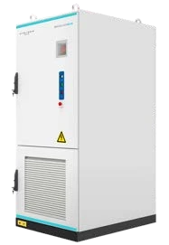
The SOLVA range offers six commercial storage configurations, with different approaches to power conversion and connection. Choose the architecture around your electrical system, inverter arrangement and operating priorities, then compare the capacity and ratings of the relevant models.
What do AC, DC and RT mean?
AC models integrate AC power conversion, DC models connect to an external inverter, and RT261 uses a rectifier-based dual-conversion arrangement. The number indicates the capacity class. DC208, for example, has 208.8kWh of total energy. These distinctions help identify which equipment is included and what the wider project must provide.
| Model | Capacity class | Configuration |
|---|---|---|
| DC208 | 208kWh | DC-coupled with external inverter integration |
| AC261 | 261kWh | Integrated PCS |
| DC261 | 261kWh | DC-coupled with external inverter integration |
| RT261 | 261kWh | Dual conversion |
| AC418 | 418kWh | Integrated 690VAC PCS |
| DC418 | 418kWh | High-voltage DC-coupled |
Configuration overview from the SOLVA technical brochure.
When should you investigate an AC model?
SOLVA AC models incorporate a power conversion system, or PCS. AC261 and AC418 support AC-bus parallel arrangements, subject to the system design. AC418 uses a 690V AC architecture for integration with a medium-voltage step-up transformer. Match the cabinet’s connection requirements to the site infrastructure when comparing proposals.
Ask the project team how the selected AC model connects to the site, what switching equipment is required and which operating modes the proposal includes. The same capacity label does not establish that two configurations can be substituted in an existing design.
How do the DC models fit into a system?
DC208, DC261 and DC418 use an external inverter. DC parallel arrangements can extend to 12 cabinets, subject to the selected model and system design. Specify the inverter, voltage range, communications and operating limits alongside the batteries so the complete installation can be assessed.
What distinguishes RT261?
RT261 uses a dual-conversion architecture with independent grid-based charging and an isolated load bus. This arrangement can be considered where grid quality is a design concern. Have the designer explain the charging and load-supply paths, and how the proposed equipment will meet the site’s operating requirements.
Read the power label as carefully as the number
AC261 includes a 125kW PCS; DC261 has a 125kW DC busbar rating; RT261 includes a 125kW rectifier. Those ratings describe different functions. Identify the battery connection, charging equipment and load-side inverter in each proposal so you can compare the actual supply to your loads.
The larger models follow the same distinction. AC418 includes a 215kW PCS, while DC418 has a 210kW DC busbar connection for an external inverter. Compare the complete equipment schedules and the output available to the site, not just the largest power figure beside each model name.
Start with the connection boundary
A good comparison identifies where each supplier's equipment ends and the rest of the site begins. For an integrated AC cabinet, ask for the AC connection details and the included conversion equipment. For a DC cabinet, identify the external inverter and the responsibility for integrating it with the battery. For RT261, ask the designer to show the charging path and the separate path supplying the loads. A simple system drawing can make these differences clearer than a list of headline ratings.
Keep those boundaries consistent when comparing quoted power. The inverter's load-side output, the rectifier's charging function and the DC busbar connection serve different purposes. They should appear as separate labelled items in the proposal. This also helps when deciding which party will provide commissioning, monitoring and technical support for the complete installation.
Use energy arithmetic to frame the discussion
Consider an illustrative business load averaging 40kW for four hours. Its load-side energy requirement is 160kWh, calculated as 40 × 4. That number is useful for a project brief, but it does not identify the appropriate SOLVA model. The design still needs to account for the operating reserve, allowed discharge, conversion and auxiliary losses, changing load and required starting power.
Now consider a different site using the same 160kWh across only two hours. Its average load would be 80kW. The energy total is unchanged, yet the average power requirement has doubled. This example explains why buyers should bring both a load profile and a duration requirement to a SOLVA comparison. It does not establish that either site can be supplied by a particular cabinet or inverter.
The guide to battery kW and kWh explains this distinction in more detail. Once the load requirement is clear, the individual DC208 guide and AC418 versus DC418 comparison help narrow the architecture and capacity discussion.
Write down the operating modes that matter
A project brief should distinguish normal grid-connected operation from any proposed backup or off-grid operation. Ask what changes when the grid is unavailable, which loads remain supplied, and how charging is managed in each mode. If solar or a generator is involved, have those connections included in the equipment schedule and operating description.
Also describe who will use the monitoring system. A facility manager may need a clear operating overview, while a commissioning technician needs the model-specific records and configuration documentation. Agree which information is handed over to each person. This is a practical way to connect the technical design with the business's daily use of the system.
Compare expansion and service access explicitly
For a staged project, request a description of the first installation and the later expansion separately. State whether the objective is more stored energy, more power, a longer backup period or a new operating mode. The design changes required for those objectives may differ. Do not assume that a cabinet-count limit quoted for one model or operating mode applies to every SOLVA configuration.
Ask the proposal to identify the site provisions for additional equipment and the documentation needed before a later stage proceeds. Likewise, have the installer explain access for inspection and maintenance using the current installation requirements. These questions support a useful shortlist without turning a general range comparison into an installation design.
Compare the complete proposed system
Request a clear equipment schedule and identify the documents supporting each component. Review capacity, inverter power, controls, installation requirements and future expansion together. The commercial storage planning guide provides a checklist of site information to gather first.
Use the download centre to retain access to the current range documents and warranties. For assistance with a specific model combination, contact Freedom Won Australia with your proposed equipment and project requirements.
Prepare a shortlist that can be checked
Record the intended operating mode, existing site voltage, planned inverter arrangement and future capacity requirement. A designer can then narrow the choice using those requirements. Follow the individual model guides below to examine the relevant specification in greater detail.
For a SOLVA shortlist, contact Freedom Won Australia with the existing equipment schedule, intended operating modes and load profile. Name the models being considered so the team can direct you to the appropriate technical documents.
Frequently asked questions
Does a SOLVA DC model include the external inverter?
DC models require an external inverter. The project equipment schedule should name that inverter and state whether it is included in the quoted supply.
Where can I find the detailed SOLVA specifications?
Open the SOLVA brochure and model-specific documents in the download centre. Confirm the applicable revision with Freedom Won Australia when preparing your proposal.
Is RT261 an AC261 with a different name?
No. RT261 has an integrated rectifier and a dual-conversion arrangement. AC261 has an integrated PCS. Their charging and power-conversion paths differ and must be assessed as complete systems.